Tecbor® Boards - Constructive Solutions
Tecbor® Boards - Non-Structural Elements - Walls
Non-structural walls, which separate fi re areas, should be fire resistant as stipulated in standard EN 1364-1.
When in fire resistance tests for non-structural elements one edge is left free (Part 1: Walls), the standard allows increasing the width.
With regard to increasing the height, the standard is clear and precise. When the test is run at least at 3 metres high, it may be increased up to 4 metres.
Very often, internal partitions are higher than 4 metres. mcr tecresa® have been the first to develop large partitions and offers the most efficient and convenient solution for this type of works.
Besides, penetrations produced between different fire sectors must be sealed off; for example, in the case of services crossing. Check the TECSEL® Sealing System catalogue to find the most suitable solution.


| TEST
Standard : UNE EN 1364-1 |
SOLUTION
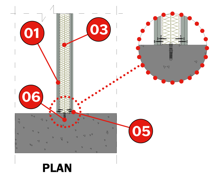
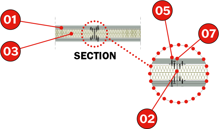
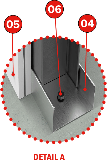
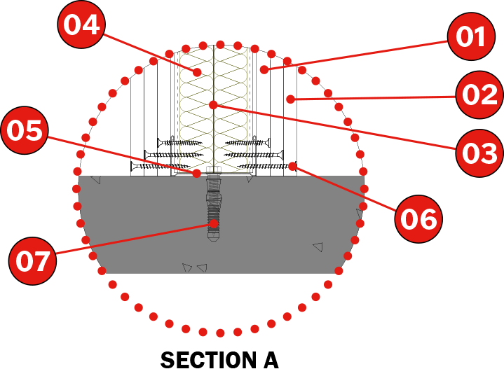
1. Tecbor® A 12 mm boards. 5. Metal plug ( M10 x 100 ). |
Description of Assembly
Fix the 73 x 30 x 0,5 mm runners using M10 metal plugs every 250-300 mm. Complete the steel structure with 70 x 36 x 0,5 mm double studs placed at the “H” position, spaced 610 mm apart.
Then fix Tecbor® 12 mm boards to both sides with 3,5 x 35 mm self-tapping screws every 200-250 mm.
Finally, cover the joints between the boards and screw using Tecbor® joint paste.
The studs are then covered with Tecbor Board strips, to which the boards will be screwed.
 |
 |
Product document

| TEST
Standard : UNE EN 1364-1 |
SOLUTION
1. Tecbor® A 12 mm boards. |
Description of Assembly
Fix the 73 x 30 x 0.5 mm runners using M6 metal plugs every 250-300 mm. Complete the steel structure with 70 x 36 x 0.6 mm double studs placed at the ‘H’ position, spaced 610 mm apart.
Position the rock-wool boards between the studs.
Then fix Tecbor® 12 mm Boards to both sides with 3.5×35 mm self-tapping screws every 200-250 mm.
Finally, cover the joints between the boards and screw heads using Tecbor® Joint Paste.
 |
 |

Product document

| TEST
Standard : UNE EN 1364-1 |
SOLUTION
1. Tecbor® 10 mm boards. |
Description of Assembly
Fix the 73x30x0.5 mm runners and assemble the 70x36x0.6 mm studs every 610 mm. Fill the framework with 80 mm (40+40 mm), 40 kg/m3
rock-wool boards.
Attach the 2 layers of Tecbor® 10 mm Boards using 3.5 x 35 mm self-tapping screws spaced 200 – 250 mm apart, butting up the layers.
Apply Tecbor® Joint Paste or Tecbor® Bonding Compound to the board joints and screw heads.
 |
 |
Product document

| TEST
Standard : UNE EN 1364-1 |
SOLUTION
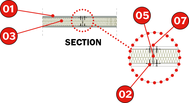
1. Tecbor® 15 mm boards. 7. 6 mm strike anchor, every 600 mm. |
Description of Assembly
Fix the 48 x 40 x 0.6 mm runners and assemble the 46 x 40 x 0.6 mm studs every 600 mm. Fill the framework with 80 mm (40+40 mm), 40 kg/m3
rock-wool boards.
Attach the 2 layers of Tecbor® 15 mm Boards with 3.5 x 35 mm self-tapping screws spaced 200 – 250 mm apart, butting up the layers. Apply Tecbor® Joint Paste or Tecbor® Bonding Compound to the board joints and screw heads.
 |
 |
Product document

| TEST
Standard : UNE EN 1364-1 |
SOLUTION
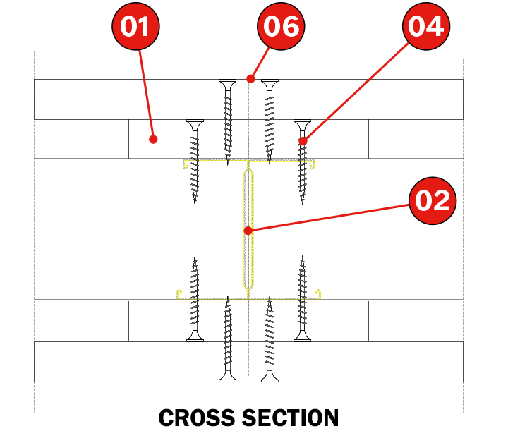
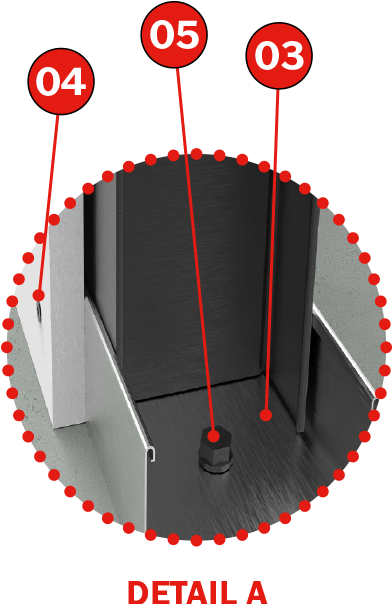
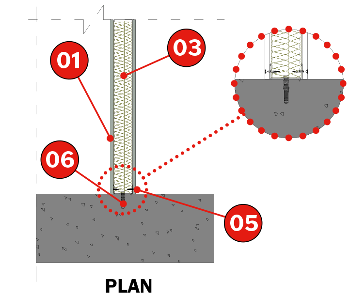
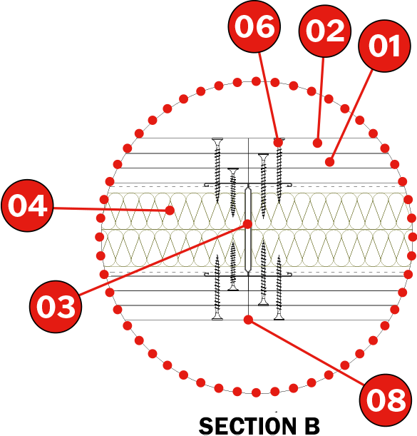
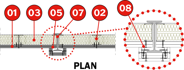
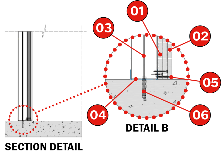
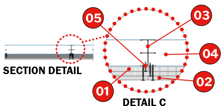
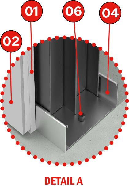
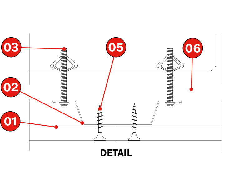
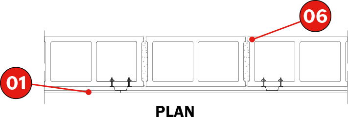
1. Tecbor® 12 mm boards. 6.Tecbor® joint paste. 9. M6 metal plug. |
Description of Assembly
Fix the 73x30x0.5 mm runners and assemble the 70x36x0.6 mm studs every 610 mm. Fill the framework with 80 mm (40+40 mm), 40 kg/m3
rock-wool boards.
Attach the 2 layers of Tecbor® 12 mm Boards using 3.5 x 35 mm self-tapping screws spaced 200 – 250 mm apart, butting up the layers.
Apply Tecbor® Joint Paste to the board joints and screw heads.
An IPN 140 metal profile was placed in the centre of the test furnace frame.
Product document

| TEST
Standard : UNE EN 1364-1 |
SOLUTION
1. Tecbor® 15 mm boards. 6. 6 mm strike anchor, every 600 mm. |
Description of Assembly
Fix the 83x40x0.6 mm runners and assemble the 34.8x40x0.6 mm studs every 600 mm.
Attach the 2 layers of Tecbor® 15 mm Boards using 3.5 x 35 mm self-tapping screws spaced 250 mm apart, butting up the layers.
Apply Tecbor® Joint Paste or Tecbor® Bonding Compound to the board joints and screw heads.
 |
 |
Product document

| TEST
Standard : UNE EN 1364-1 |
SOLUTION
1. Tecbor® 10 mm boards. 6. Concrete block wall. |
Description of Assembly
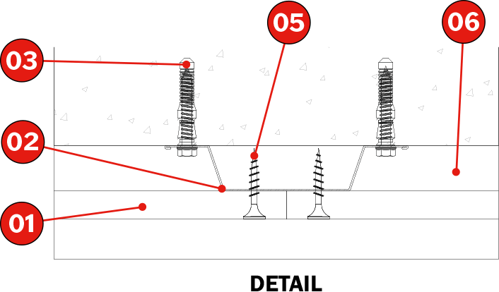
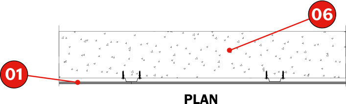
On a 15 cm precast concrete wall, fix the 15 x 45 x 0.5 mm omega profiles every 610 mm using a 5 x 65 mm umbrella anchors. Then attach the Tecbor® 10 mm Boards to the omega profiles using 3.5 x 25 mm self-drilling screws.
Apply Tecbor® Joint Paste to the board joints and screw heads.
The screws must be spaced approximately 250300 mm apart.
Product document

| TEST
Standard : UNE EN 1364-1 |
SOLUTION
1. Tecbor® 12 mm boards. 6. Precast concrete slab. |
Description of Assembly
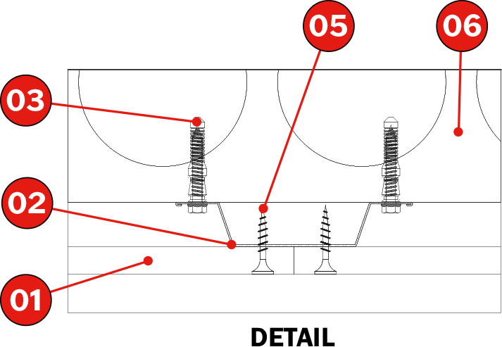
On a 12 cm precast concrete wall, fix the 15 x 45 x 0.5 mm omega profiles every 610 mm using a 5 x 65 mm metal plug.
Then attach the Tecbor® 12 mm Boards to the omega profiles using 3.5 x 25 mm self-drilling screws.
Apply Tecbor® Joint Paste to the board joints and screw heads. The screws must be spaced approximately 250300 mm apart
Product document

| TEST
Standard : UNE EN 1364-1 |
SOLUTION
1. Tecbor® 12 mm Boards. 7. 10 mm plastering. |
Description of Assembly
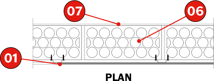
On a wall made of 12 cm ceramic brick, plastered with 10 mm of plaster on the non-exposed side, attach 15 x 45 x 0.5 mm metal omega profiles every 610 mm using 10 x 60 mm anchors. Then attach the Tecbor® 12 mm Boards to the omega profiles using 3.5 x 25 mm self-drilling screws.
Apply Tecbor® Joint Paste to the board joints and screw heads.
The screws must be spaced approximately 250 – 300 mm apart.
Product document
Do you have any questions about the product?
Learn More About
Partition wall/large format cladding with: