Tecbor® Boards - Constructive Solutions
Tecbor® Boards - Suspended Ceilings and Slabs Protection
Fireproof suspended ceilings are used mainly in two specific cases:
- The first case is to isolte different fire sectors vertically. This action helps restrain fire to its starting point and avoids its propagation to other areas. This solution is highly useful in the case of hihg-rises since partial sector division might cause the fire to spread easily causing serious problems during evacuation.
- The second case is to protect the various objects found above the ceiling; for example, installations, structures, slabs, etc.
According to our requirements, we shall use either application. Our solutions have been tested when fire strikes from below.


| TEST
Standard: UNE EN 1364-2 |
SOLUTION
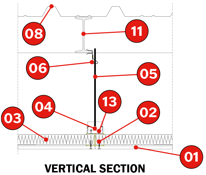
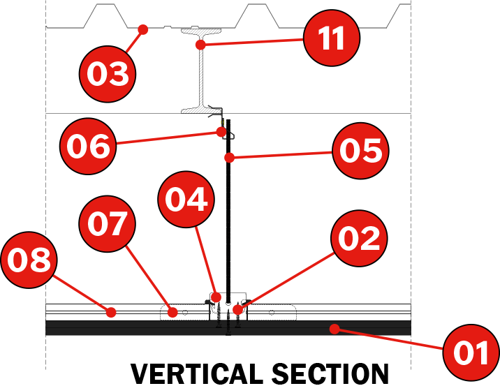
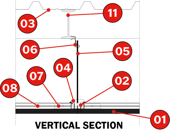
1. Tecbor® 12 mm boards. 7. TC 60/27.
|
Description of Assembly
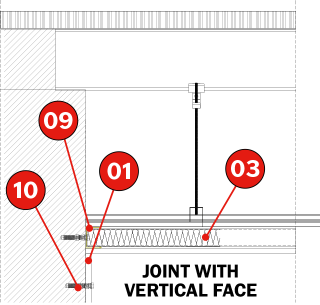
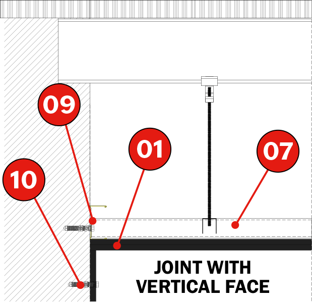
Fix the 48 x 30 x 0.5 mm runners using 10 x 100 mm plugs spaced approximately 500 mm around the entire perimeter of the ceiling.
Next, place the TC 60/27 profiles at a distance of 610 mm transversely between axes, and cross the profiles using a splice connection for TC 60/27, forming a 610 × 610 mm grid. Using the clevis joints, M6 rod and fastening clamp, attach the structure to the support on which the ceiling is hung.
Once the metal structure is finished, attach the first layer of Tecbor® 12 mm Boards, alternating the placement of 40 mm, 40 Kg/m3 rock-wool, on top of the metal structure. Once the metal structure is finished, attach the first layer of Tecbor® 12 mm Boards, alternating the placement of 40 mm, 40 Kg/m3 rock-wool, on top of the metal structure. Next, assemble the second layer of Tecbor® Boards using 3.5 x 45 mm self-tapping screws. This second layer is butted to the first. Finally, finish off the perimeter with a 150 mm wide skirting using Tecbor® 12 mm.
The distance between screws must be approx. 250-300 mm and the screw heads and board joints must be covered with Tecbor® Joint Paste
 |
|
Product document

| TEST
Standard: UNE EN 1365-2 |
SOLUTION
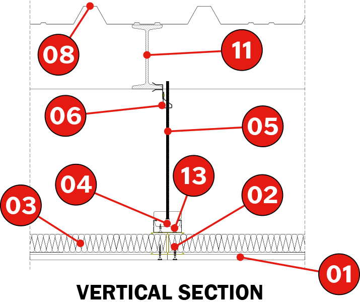
1. Tecbor® 12 mm boards. 7. TC 60/27. |
Description of Assembly
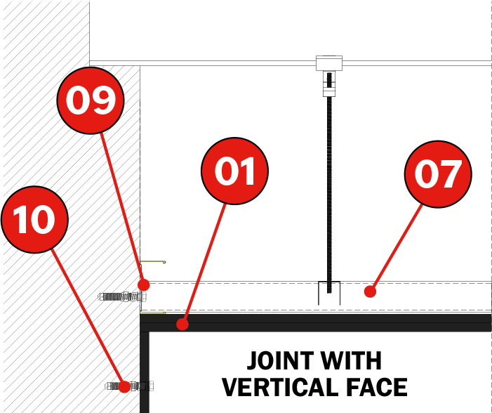
Fix 48x30x0.5 mm runners with 10×100 mm plugs every 500 mm approximately around the ceiling’s perimeter. Next place profiles made up of 246x36x0.6 mm studs arranged in “H” position lying down. Put the rock wool panels in between. Studs are fixed to TC 60/27 profiles by the upper part and suspended from the slabs through a hanging system including a Steel grip, an M6 rod and clamps every 600 mm approximately. Inter-section joints are connected through 2.9×13 mm metal/metal selfdrilling screws.
Then Tecbor® 12 mm boards are fixed using 3.5×35 mm screws every 250-300 mm. The work is completed with a 150 mm baseboard of Tecbor® 12 mm placed all around the perimeter.
Distance between screws will be approximately 250-300 mm.
Screw heads and inter-board joints will be covered with Tecbor® joint paste.
On top of the suspended ceiling and the IPE 140 metal profiles a 0.6 mm thick ribbed sheet was placed at 400 mm.
 |
 |
Product document

| TEST
Norma: UNE EN 1365-2 |
SOLUTION
1. Tecbor® 12 mm boards. 7. TC 60/27. |
Description of Assembly
Fix 73x30x0.5 mm runners with 10×100 mm plugs every 500 mm approximately around the ceiling’s perimeter. Then install TC 60/27 profiles at a distance of 610 mm between axes placing such sections crosswise through a Steel grip for TC 60/27 forming 610×610 mm frames. Using the steel grip, the M6 rod and the clamps, fix the structure to the one supporting the ceiling.
Attach both Tecbor® 12 mm board layers with 3.5×45 mm self-tapping screws. Then alternate the second Tecbor® board with the first one.
Use Tecbor® 12 mm to finish off the assembly with a 150 mm wide base-board around the perimeter.
Distance between screws will be approximately 250-300 mm. Screw heads and inter-board joints will be covered with Tecbor® joint paste.
On top of the suspended ceiling and the IPE 160 metal profiles a 0.6 mm thick ribbed sheet was placed at 550 mm.
 |
 |
Product document

| TEST
Standard: UNE EN 1365-2 |
SOLUTION
1. Tecbor® 15 mm boards. 7. TC 60/27. |
Description of Assembly
Fix the 73 x 30 x 0.5 mm runners using 10 × 100 mm plugs spaced approximately 500 mm around the entire perimeter of the ceiling. Next, place the TC 60/27 profiles at a distance of 610 mm transversely between axes, and cross the profiles using a splice connection for TC 60/27, forming a 610×610 mm grid, using the clevis, M6 rod and fastening clamp to join the structure to the support on which the ceiling is hung.
Once the metal structure is complete, attach the two layers of 15 mm Tecbor® using 35 x 45 mm self-tapping screws. The second layer of Tecbor® is butted to the first.
Finally, finish off the perimeter with a 150 mm wide skirting using Tecbor® 15 mm. The distance between screws must be approx. 250-300 mm and the screw heads and board joints must be covered with Tecbor® Joint Paste.
A 0.6 mm-thick corrugated sheet is placed above the suspended ceiling, at a distance of 550 mm, and on top of the IPE 160 metal profiles.
 |
 |