Tecbor® Boards - Constructive Solutions
Tecbor® Boards - Steelwork Protection
Steel structures are used for building purposes worldwide. One of the main advantages is that they have great resistance per weight unit, which provides them with huge versatility and the possibility of creating complex yet light
structures.
However, the thermal conductivity of steel represents a disadvantage. Therefore, in the event of a fire, the gradual increase in temperature plus steel high heat transmission result in a substantial reduction of the structure’s bearing capacity and mechanical resistance.
The resistance and elastic limit are modified above 250°C, and above roughly 500°C the drop in resistance is signifi cant enough not to support its design capacity.
mcr tecresa® has conducted numerous tests with Tecbor® according to UNE EN 13381-4, standard, in which is determined the contribution of fire protection of the board when we protect steel structural elements, either on
beams, columns or bearing elements.
Tecbor® has been tested to cover a great variety of steel profiles characterised by their section factors. Likewise, it has been tested for several standard specifi ed design temperatures.

Product document

| TEST
Standard :UNE ENV 13381-4 |
SOLUTION
1. Tecbor® boards. |
Description of Assenbly
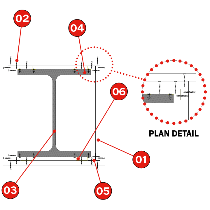
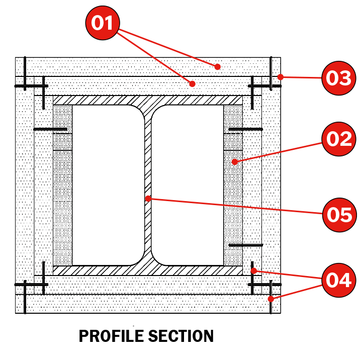
Fix 45x15x0,6 mm omega profiles to the outer side of the flange of the metal profile to be protected using steel nails at a maximum of 725 mm between each nail.
Fix 30x30x0,6 mm lower angle section to the Tecbor® board strips and these onto the omega profiles and onto the angle anchored to the slabs with self-tapping screws every 250 mm. Assemble the strips.
Apply Tecbor® joint paste to the screw heads and board joints.
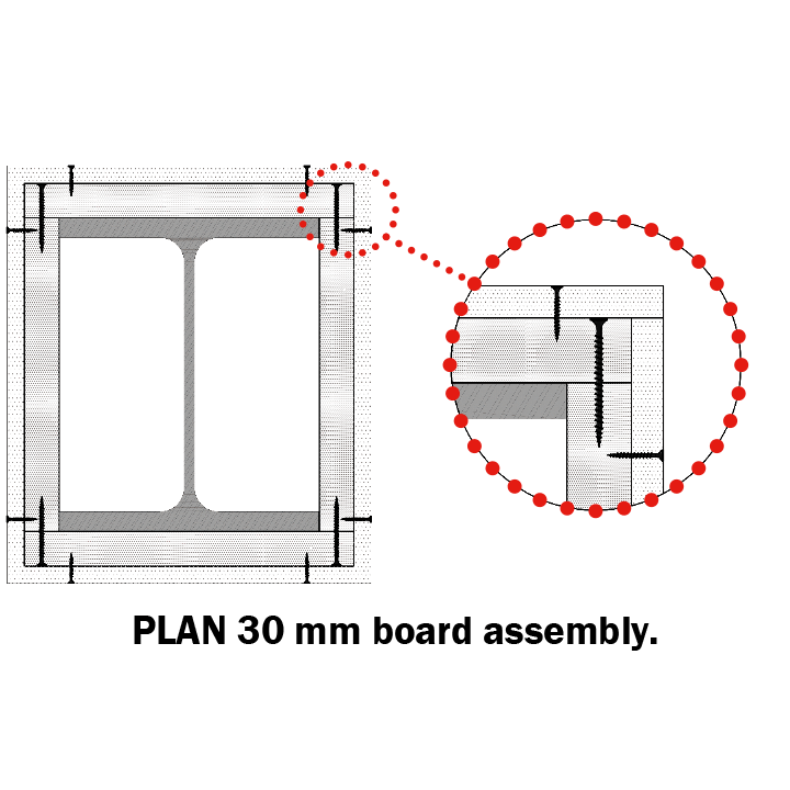
NOTE: If the protection procedure comprises Tecbor® boards with a thickness equal to or greater than 30 mm, they may be joined without auxiliaries using 5 x 80 mm screws at intervals of 250 mm.
 |
 |

| TEST
Standard :UNE ENV 13381-4 |
SOLUTION
1. Tecbor® boards. |
Description of assembly
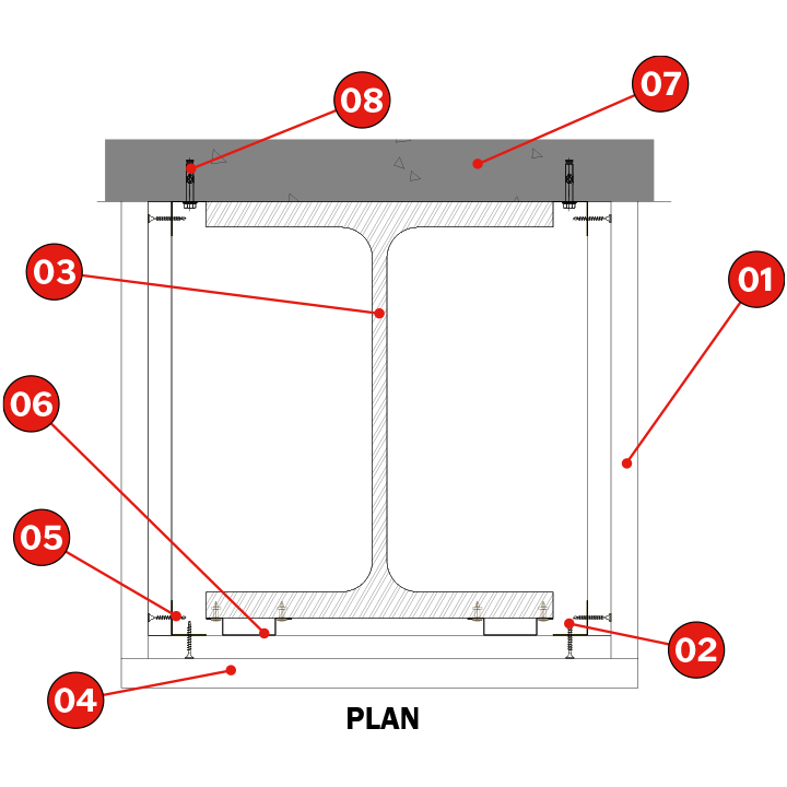
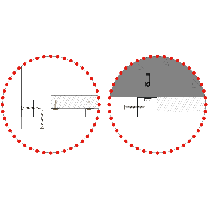
Fix 45x15x0.6 mm omega profiles to the outer side of the metal profile’s fl ange to be protected with steel nails every 725 mm.
Fix 30x30x0.6 mm lower angle section to the Tecbor® board strips and these onto the omega profiles and onto the angle anchored to the slabs with self-tapping screws every 250 mm.
Apply Tecbor® joint paste to the screw heads and board joints.
 |
 |

| TEST
Standard :UNE ENV 13381-4 |
SOLUTION
1. Tecbor® boards. |
Description of assembly
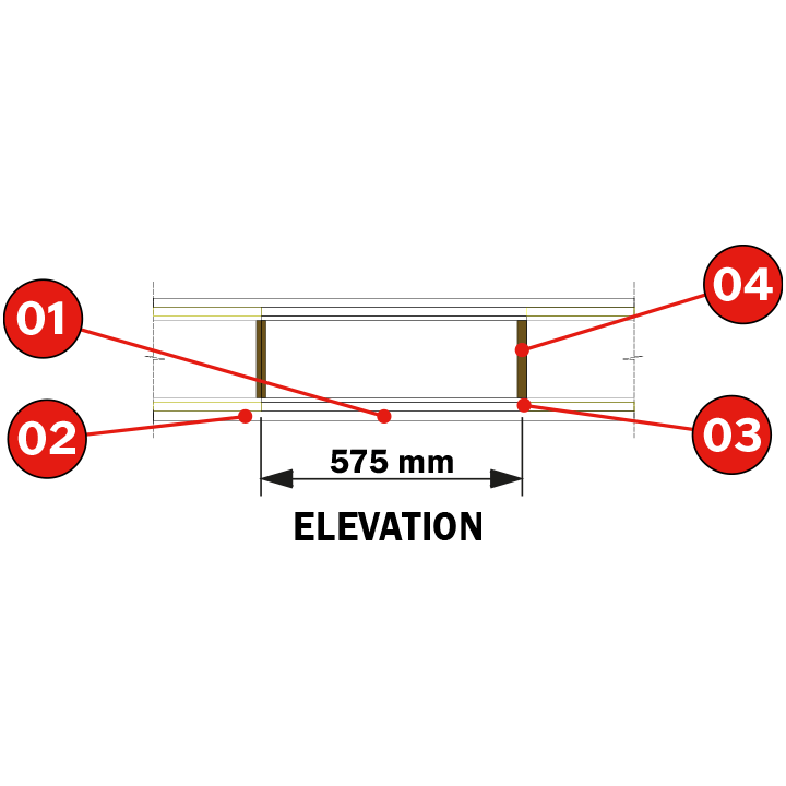
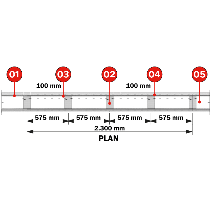
Fix the 45 x 15 x 0.6 mm omega profiles to the outer side of the flange of the metal profile to be protected using steel nails, and form a ring around it.
The rings will be separated at intervals of a maximum of 575 mm. They will be placed in such a way that the horizontal joints between plates overlap on an omega profile.
Screw the Tecbor® boards to the omega profiles using self-tapping screws every 250 mm.
Apply Tecbor® joint paste in screw heads and between boards.
 |
 |

| TEST
Standard :UNE ENV 13381-4 |
SOLUTION
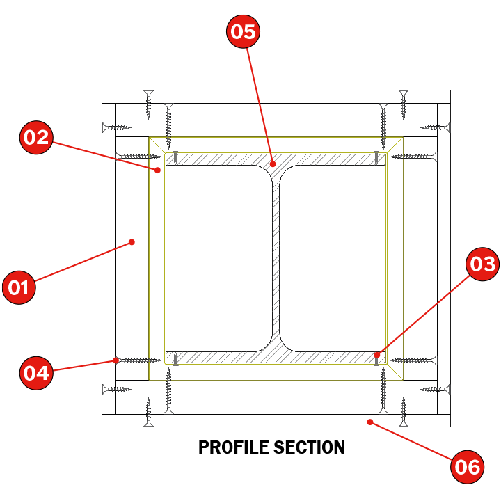
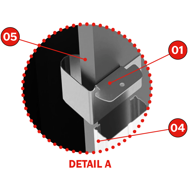
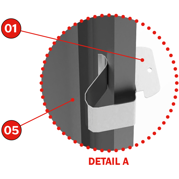
1. Clip Tecbor®. |
Description of Assembly
Attach the Tecbor® clip to the outer side of the metal profiles to be protected, separated at intervals of no more than 500 mm.
Attach the 45 x 18 x 0.6 mm TC roof profiles to the Tecbor® clip by applying pressure.
Attach the Tecbor® boards to the TC profiles using self-tapping screws every 250 mm.
Use Tecbor® joint paste in screw heads and between boards.
 |
 |

| TEST
Standard :UNE ENV 13381-4 |
SOLUTION
1. Tecbor® Boards. |
Description of Assembly
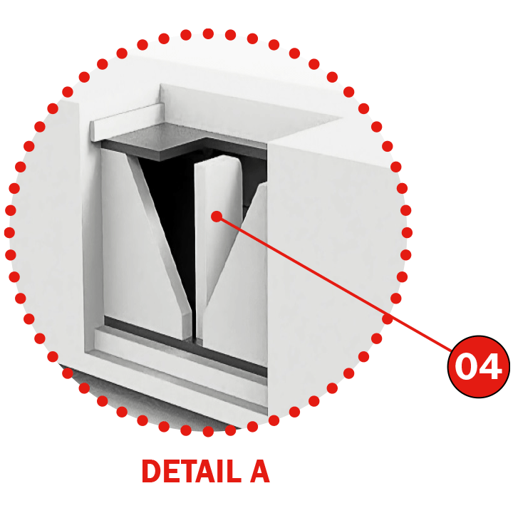
Cut stiffeners using Tecbor® 20 mm Boards, adaptedto the measurements of the metal profile to be protected. Insert them perpendicular to the axis of the profile at intervals of no more than 575 mm.
Cut Tecbor® Board strips adapted to the measurement between the flanges of the metal profile to be protected. Attach these strips to the stiffeners using self-tapping screws, so that the joint between the boards overlaps on a supporting
stiffener.
Attach the Tecbor® Boards of a thickness equal to or greater than 20 mm to each other and anchored onto the board strips using self-tapping screws every 250 mm.
Apply Tecbor® Joint Paste to the screw heads and board joints.
 |
 |

| TEST
Standard :UNE ENV 13381-4 |
SOLUTION
1. Tecbor® Boards. |
 |
 |
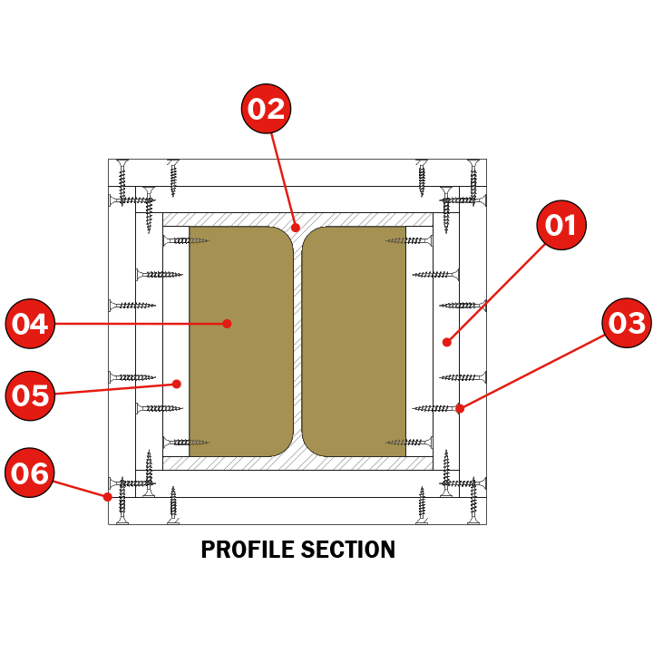
Description of Assembly
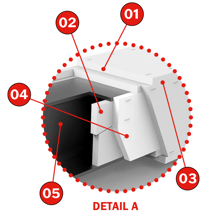
Cut stiffeners using Tecbor® 20 x 100 mm Boards, adapted to the measurements of the metal profile to be protected. Insert them using a wedge as indicated in the detailed plans at intervals of no more than 600 mm.
Attach the Tecbor® side Board to the support plugs so that the joints between the boards overlap on a support plug. These Tecbor® lateral Boards are attached using metal clamps separated at intervals of 50 mm on board joints.
For beams only, a stiffener made using 20 x 100 mm Tecbor® Boards must be fixed to the Tecbor® lateral Boards by means of metal clamps, fixed to the underside of the profile to be protected
Attach the lower Tecbor® Boards to the lateral boards and to the lower stiffeners using metal clamps spaced at intervals of no more than 100 mm.
Clamps of a length equal to or greater than the total thickness of the boards must be used; the minimum dimensions required are 35 x 10.6 x 1.6 mm.
 |
 |
Do you have any questions about the product?
Learn More About
Steelwork Protection with: