Tecbor® Boards - Ventilation & smoke extraction ducts
The regulatory requirements demand the compartment of elements when traversed by installations, such as pipes or extraction and ventilation ducts.
- Fire resistance required to the fire compartment elements must be kept on the points where such elements are traversed by installation materials, such as cables, pipes, ducts, ventilation ducts, etc. To that end, a choice can be made between the following alternatives:
- Put an element which, in case of a fire, automatically blocks the cross section and guarantees in such point a fire resistance at least equal to that of the traversed element, for example, an automatic firewall dumper. The t (i↔o) being the fire resistance time required to the traversed compartment element, or a blocking intumescent device.
- Crossing elements which provide a resistance at least equal to that of the traversed element, for example, EI ventilation ducts t (i↔o)
being t the fire resistance time required to the traversed compartment element
From the previous paragraph follows that the fire resistant ducts which pass through fire compartments must have the compartments from within and from the outside to it.
RSCIEI describes in its annex II Article 5.7:
“Systems including ducts, both verticals and horizontal, which traverse compartment elements and whose function doesn’t allow the use of dampers (smoke exhaust, ventilation of evacuation routes, etc.), must be fire resistant or adequately protected throughout its route with the same level of fire resistance than the traversed elements, and tested according to the applicable UNE-EN
standards”.
UNE EN applicable standards, as they appear in Annex DB SI G of the TBC are:
- UNE EN 1366 Part 1 for ventilation ducts.
- UNE EN 1366 Part 8 for multi-sector extraction ducts.

| TEST
Standard : UNE EN 1366-1 |
SOLUTION
1. Tecbor® 30 mm. boards. |
Description of Assembly
Duct composition:
Duct consisting of Tecbor® boards 30 mm thick.
Fixings between sections:
Longitudinally, the boards are joined with Tecsel® adhesive.
Laterally, the duct sections are joined with perimeter joint covers formed by Tecbor® boards 30 mm thick and 250 mm wide.
The joint covers are fixed to the section by means of 2 rows of 5 x 60 mm wood threaded screws, screwed every 250 mm along the long sides and 200 mm on the short sides. The rows are spaced 160 mm apart.
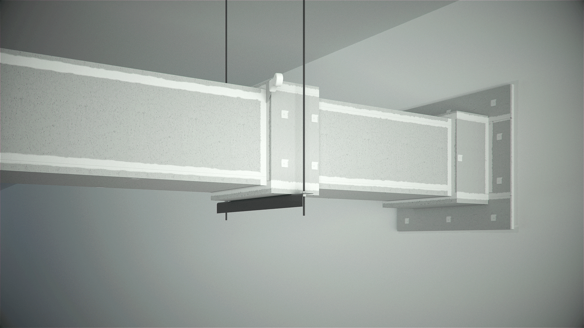
Method of duct support:
The duct is supported by an auxiliary structure made up of M16 threaded rods and 50 mm x 50 mm and 5 mm thick L-shaped upon which the duct rests. Maximum distance between the hangs will be 1200 mm.
Sealing of the penetration point through the support work. Sealing will be carried out with the following elements:
- Tecbor® boards 30 mm thick.
- Rock wool 50 mm thick and density 145 Kg/m3.

Product document

| TEST
Standard : UNE EN 1366-1 |
SOLUTION
1. Tecbor® 30 mm. boards. 10 |
Description of Assembly
The duct is made of a layer of 30 mm Tecbor® and another layer of 20 mm Tecbor®.
The first layer of boards are joined using 3.9 x 45 mm self-tapping screws.
The 20 mm board is joined to the first layer using 3.9 x 35 mm screws.
The joint between duct sections is made by covering the joint with Tecbor® 20+20 mm joint covers, 250-300 mm wide, fixed to the duct by means of 3.9 x 45 mm self-tapping screws every 250 mm.
The duct is supported on 50 x 50 x 5 mm horizontal angles and suspended from the slab by means of the M16 rod, grommet and nut assembly. The
hangings are spaced 1 m apart.
Board joints, junctions and screw heads must be applied with Tecbor® Joint Paste Ready to Use.
Compartment penetration:
The space between the duct and the supporting structure is filled with 145 kg/m³ rock-wool, then Tecbor® 30+20 mm Board strips, about 250 mm
wide, are placed around the duct and anchored to the supporting structure using 10 x 100 mm plugs on both sides.
Then we create a ring surrounding the duct with 250 mm strips attached using 3.9 x 45 mm selftapping screws.
For more information, see the installation manual.
